 Removing the Processor Module
Dell™ Latitude™ D820 Service Manual
Installing the Processor Module

|
CAUTION: Before performing the following procedures, follow the safety instructions in the Product Information Guide. |
|
|
CAUTION: To prevent static damage to components inside your computer, discharge static electricity from your body before you touch any of your computer's electronic components. You can do so by touching an unpainted metal surface. |

|
NOTICE: Press and hold the processor down by applying slight pressure to the center of the processor while turning the cam screw to prevent intermittent contact between the cam screw and processor. |
|
|
NOTICE: To avoid damage to the processor, hold the screwdriver so that it is perpendicular to the processor when turning the cam screw. |
|
|
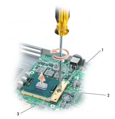
NOTICE: When removing the processor module, pull the module straight up. Be careful not to bend the pins on the processor module. |
The ZIF-socket cam screw secures the processor to the system board. Take note of the arrow on the ZIF-socket cam screw.
|
1 |
ZIF-socket |
2 |
ZIF-socket cam screw |
3 |
pin-1 corner of processor |
|
|
NOTICE: Ensure that the cam lock is in the fully open position before seating the processor module. Seating the processor module properly in the ZIF socket does not require force. |
|
|
NOTICE: A processor module that is not properly seated can result in an intermittent connection or permanent damage to the processor and ZIF socket. |
When the processor module is correctly seated, all four corners are aligned at the same height. If one or more corners of the module are higher than the others, the module is not seated correctly.
|
|
NOTICE: Hold the processor down while turning the cam screw to prevent intermittent contact between the cam screw and processor. |

|
NOTE: If a new microprocessor is installed, you will receive one of the following: a new thermal-cooling assembly which will include an affixed thermal pad; or, you will receive a new thermal pad along with a tech sheet to illustrate proper installation. |